DIM 140 Flow Through Installation Guide
The DIM 100 Flow Through installation targets checkweighers, conveyors, and rollers, where it can be easily mounted with a custom adapter plate.
You should receive
DIM 100 Dimensioner
1 meter L tube
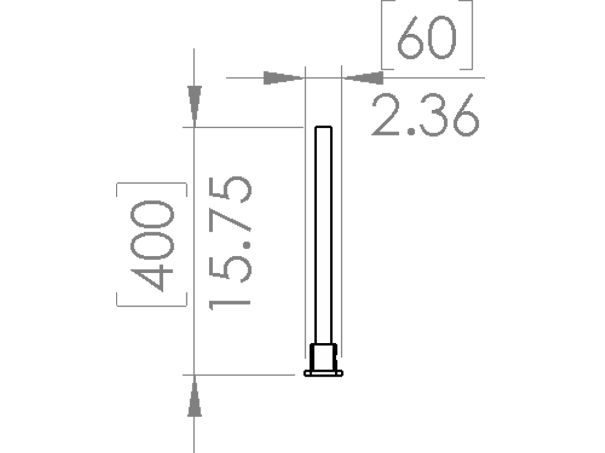
Extension tube (length varies)
And various fasteners to tighten the structure together.
If you need help figure out how to mount the dimensioner to your conveyor belt, simply Contact Us and we would love to help!
If you need help figure out how to mount the dimensioner to your conveyor belt, simply Contact Us and we would love to help!
Step 1 - Find an appropriate location for the dimensioner
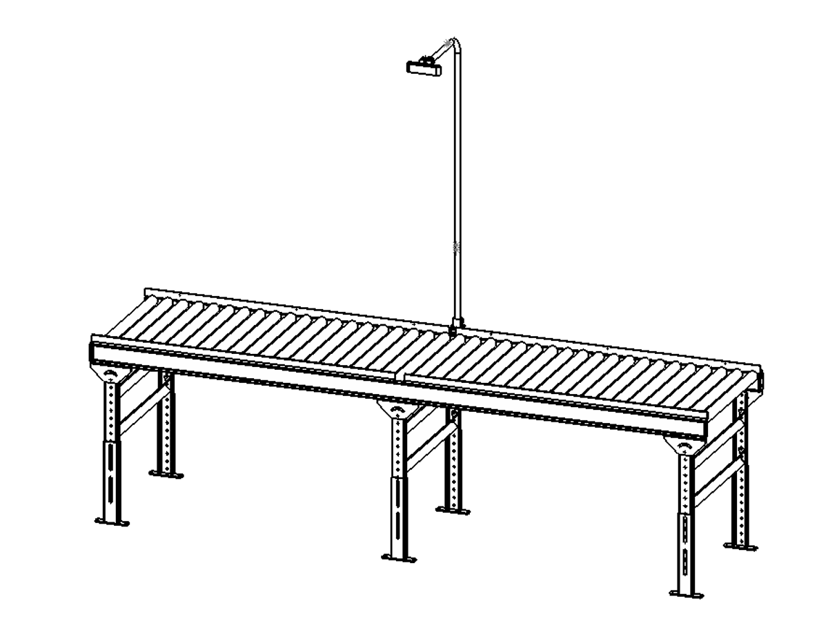
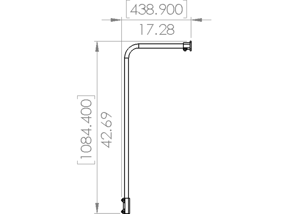
Distance between the camera array and the dimensioning surface should be 1.4m. The center of the camera should line up with the center of belt / conveyor as illustrated below.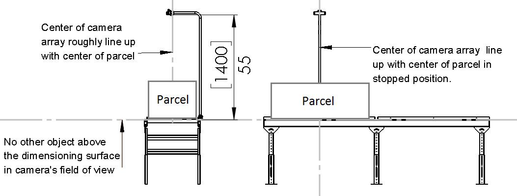 In an ideal environment, no other objects should be above the dimensioning surface within the camera's field of view. However, static objects above the dimensioning surface are allowed as long as they do not move during dimensioning.
In an ideal environment, no other objects should be above the dimensioning surface within the camera's field of view. However, static objects above the dimensioning surface are allowed as long as they do not move during dimensioning.Step 2 - Create custom mounting plate
Once an appropriate place for the dimensioner is found, a custom mounting plate need to be manufactured to fix the DIM 100 dimensioner to the conveyor belt.
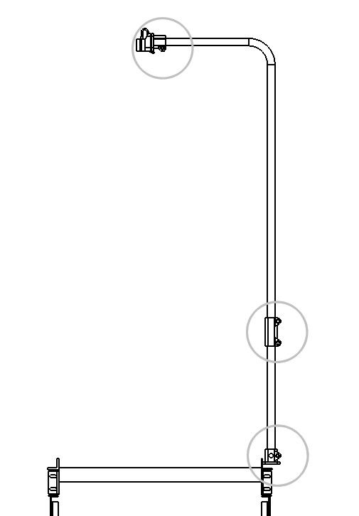
4 mounting holes are required to properly fasten the extension tube to the mounting plate. The diagram below indicates the dimensions for the mounting holes.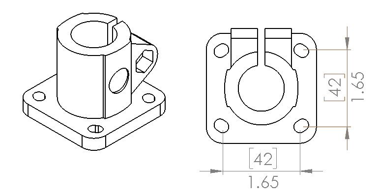
4 mounting holes are required to properly fasten the extension tube to the mounting plate. The diagram below indicates the dimensions for the mounting holes.
Step 2 - Attach the DIM 100 camera head
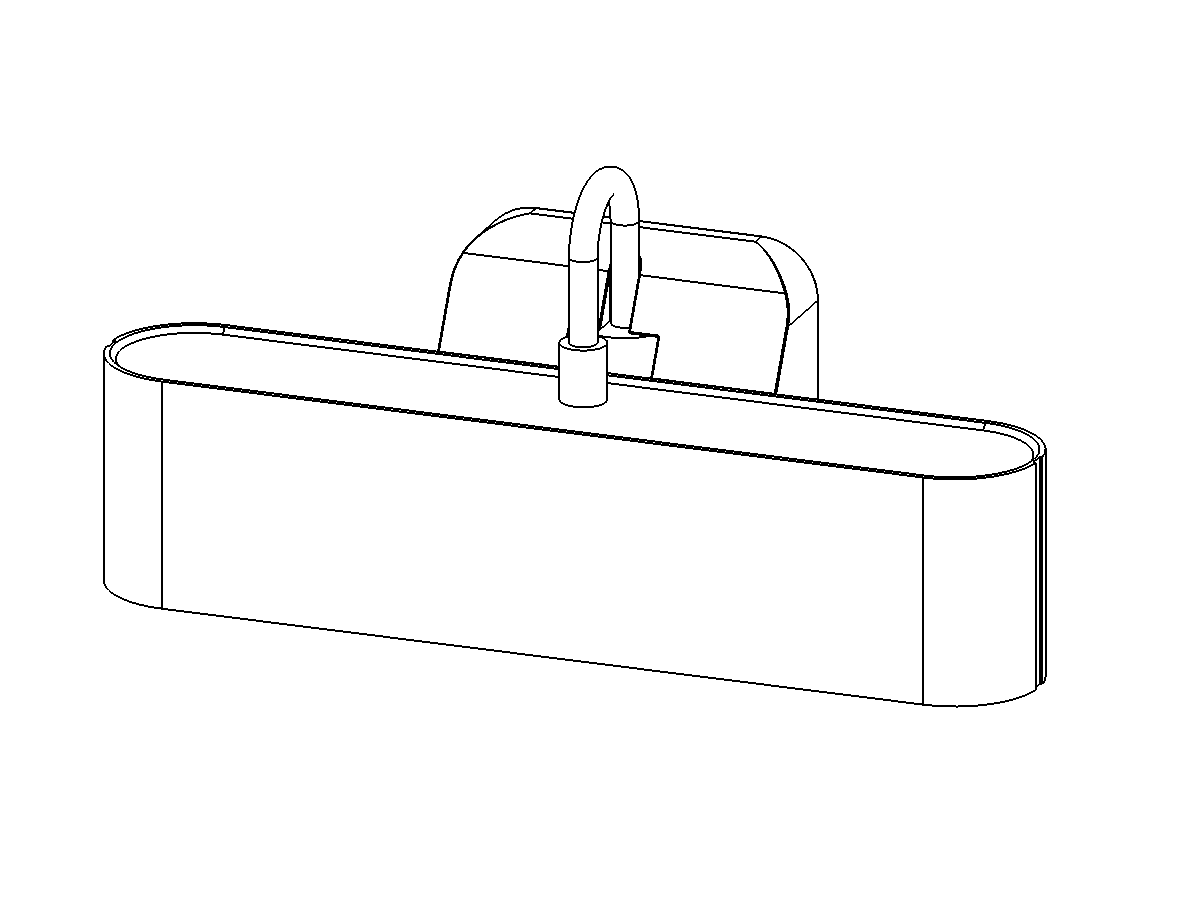
Attach the DIM 100 camera head to the top of the L tube using the 4 self tapping screws (size 14) and a #2 philips screw driver.
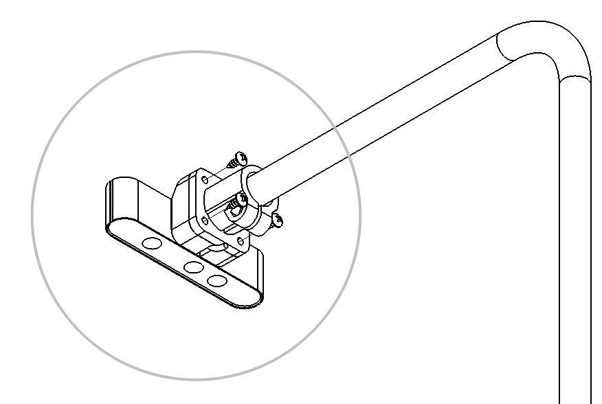 Do not over-tighten
Do not over-tightenStep 2 - Attach extension tube to L tube
Attach bottom of the L tube to the extension tube.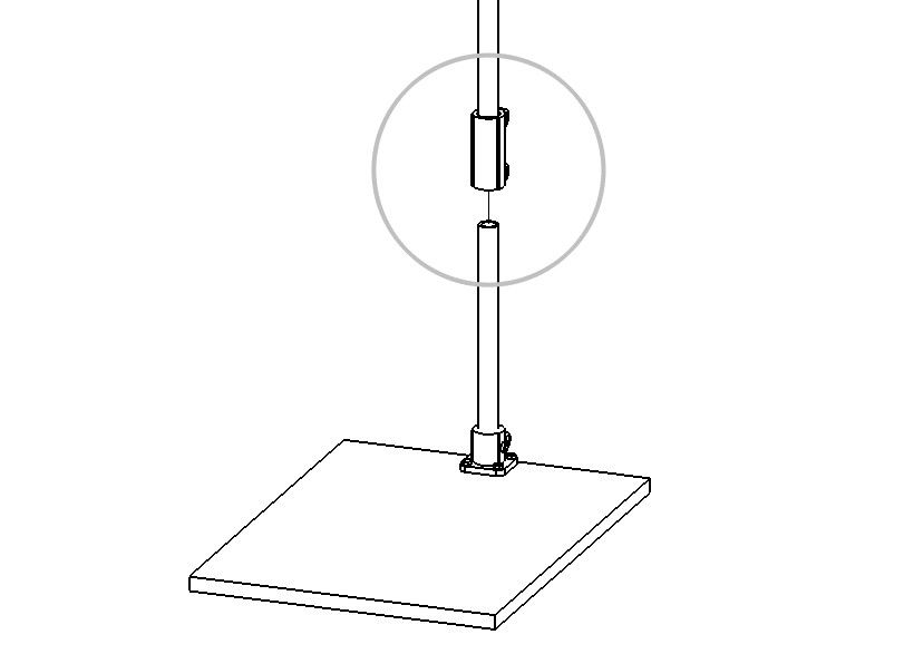
Step 4 - Tighten everything down
Make sure the camera sits parallel to the dimensioning surface and connect to the camera through the Tricolops Dimensioning App. Adjust the position of the camera as necessary, and use 5mm hex key to tighten the three connectors.